
Which one of the following matrices has an inverse?


Explanation Locked!
Unlock this branch to view the explanation, track, bookmark and more.
Sign in to UnlockThe number of junctions in the circuit is
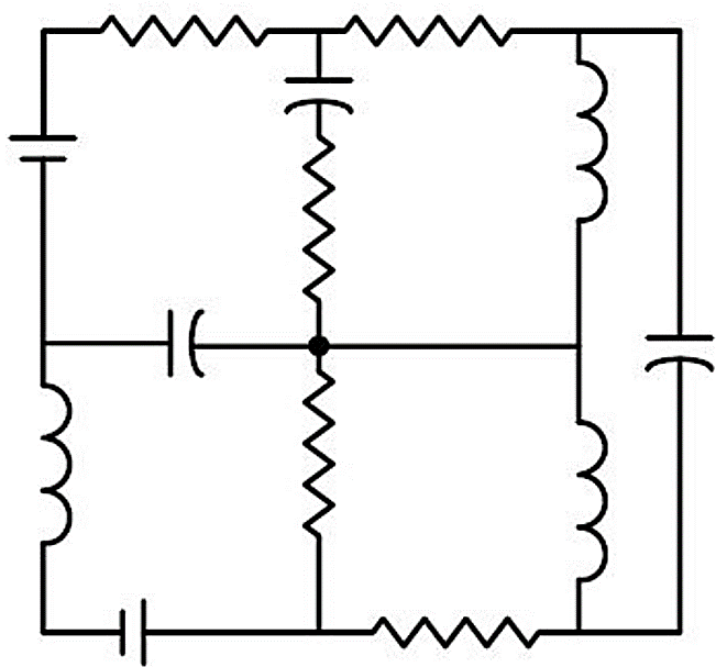
Explanation Locked!
Unlock this branch to view the explanation, track, bookmark and more.
Sign in to UnlockAll the elements in the circuit are ideal. The power delivered by the source in watts is

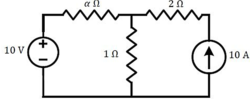
0
50
100
dependent on the value of

Explanation Locked!
Unlock this branch to view the explanation, track, bookmark and more.
Sign in to UnlockThe circuit shown in the figure with the switch S open, is in steady state. After the switch S is closed, the time constant of the circuit in seconds is
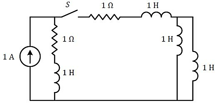
Explanation Locked!
Unlock this branch to view the explanation, track, bookmark and more.
Sign in to UnlockSuppose signal is obtained by the time-reversal of signal , i.e., . Which one of the following options is always true for the convolution of and ?


Explanation Locked!
Unlock this branch to view the explanation, track, bookmark and more.
Sign in to UnlockIf is the unit step function, then the region of convergence (ROC) of the Laplace transform of the signal is


Explanation Locked!
Unlock this branch to view the explanation, track, bookmark and more.
Sign in to UnlockA three phase, pole induction motor runs at . The stator copper loss, core loss, and the rotational loss of the motor can be neglected. The percentage efficiency of the motor is


Explanation Locked!
Unlock this branch to view the explanation, track, bookmark and more.
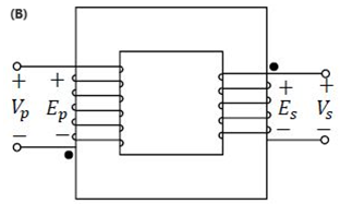
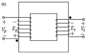
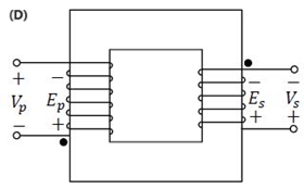
Sign in to UnlockWhich one of the following options represents possible voltage polarities in a single phase two winding transformer? Here, is the applied primary voltage, is the induced primary voltage, is the open circuit secondary voltage, and is the induced secondary voltage.


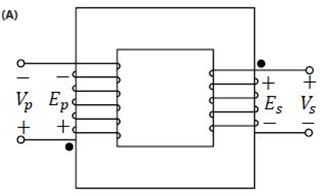
Explanation Locked!
Unlock this branch to view the explanation, track, bookmark and more.
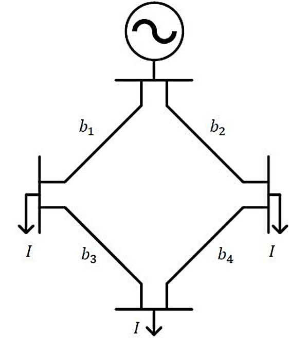
Sign in to UnlockThe figure shows the single line diagram of a 4-bus power network. Branches , , and have impedances , and per-unit (pu), respectively, where , with and . The current drawn from each load bus (marked as arrows) is equal to pu, where . If the network is to operate with minimum loss, the branch that should be opened is


Explanation Locked!
Unlock this branch to view the explanation, track, bookmark and more.
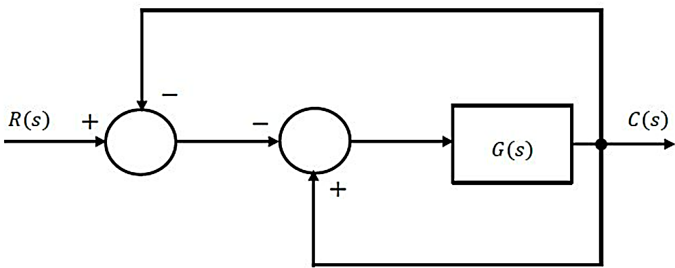
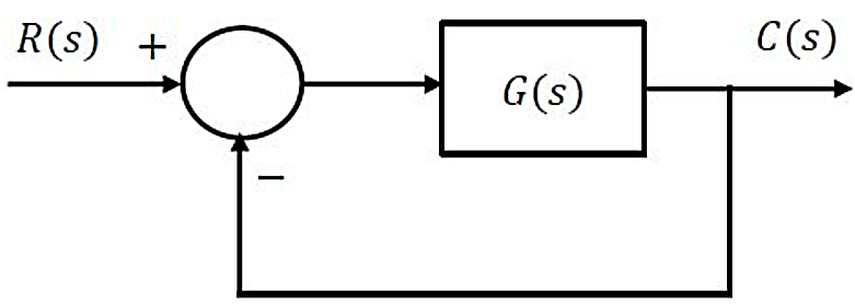
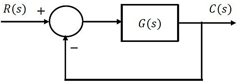
Sign in to UnlockFor the block-diagram shown in the figure, the transfer function is


Explanation Locked!
Unlock this branch to view the explanation, track, bookmark and more.
Sign in to UnlockConsider the standard second-order system of the form with the poles and having negative real parts. The pole locations are also shown in the figure. Now consider two such second-order systems as defined below:


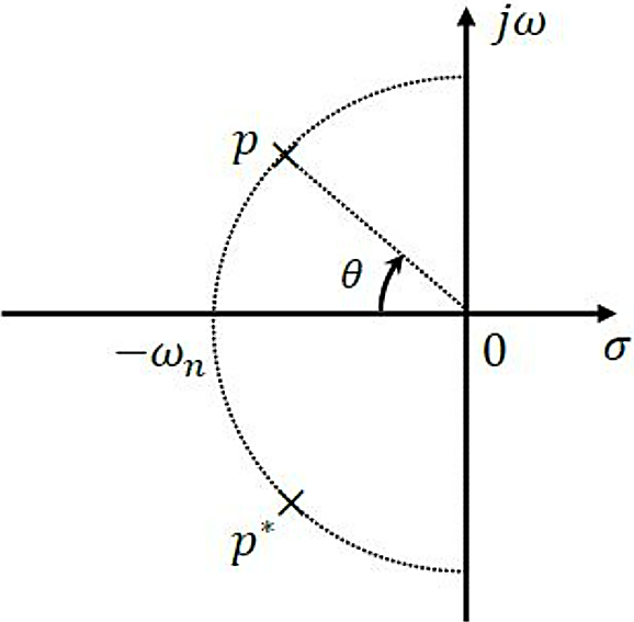
System 1: and


System 2: and


Which one of the following statements is correct?
Explanation Locked!
Unlock this branch to view the explanation, track, bookmark and more.
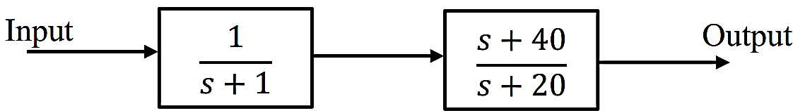
Sign in to UnlockConsider the cascaded system as shown in the figure. Neglecting the faster component of the transient response, which one of the following options is a first order pole-only approximation such that the steady-state values of the unit step responses of the original and the approximated systems are same?


Explanation Locked!
Unlock this branch to view the explanation, track, bookmark and more.
Sign in to UnlockThe table lists two instrument transformers and their features:
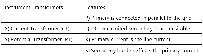
The correct matching of the two columns is
Explanation Locked!
Unlock this branch to view the explanation, track, bookmark and more.
Sign in to UnlockSimplified form of the Boolean function
Is


Explanation Locked!
Unlock this branch to view the explanation, track, bookmark and more.
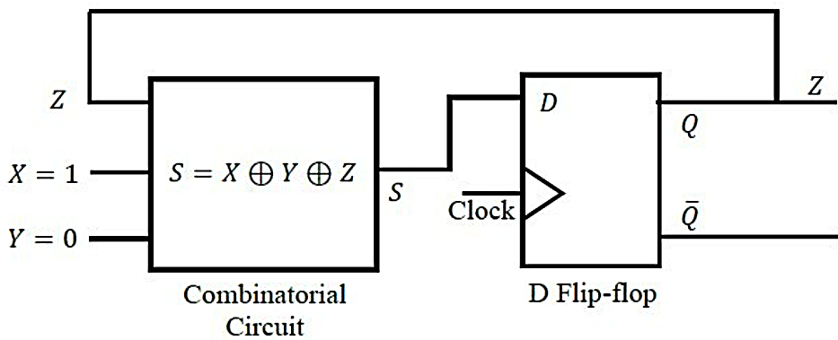
Sign in to UnlockIn the circuit, the present value of is 1. Neglecting the delay in the combinatorial circuit, the values of and , respectively, after the application of the clock will be


Explanation Locked!
Unlock this branch to view the explanation, track, bookmark and more.
Sign in to UnlockIf the following switching devices have similar power ratings, which one of them is the fastest?
Explanation Locked!
Unlock this branch to view the explanation, track, bookmark and more.
Sign in to UnlockA single-phase triac based AC voltage controller feeds a series RL load. The input AC supply is . The values of and are and , respectively. The minimum triggering angle of the triac to obtain controllable output voltage is


Explanation Locked!
Unlock this branch to view the explanation, track, bookmark and more.
Sign in to UnlockWhich of the following complex functions is/are analytic on the complex plane?


Explanation Locked!
Unlock this branch to view the explanation, track, bookmark and more.
Sign in to UnlockConsider the complex function . The coefficient of in the Taylor series expansion of about the origin is ________ (rounded off to 1 decimal place).


Explanation Locked!
Unlock this branch to view the explanation, track, bookmark and more.
Sign in to UnlockThe sum of the eigenvalues of the matrix is ________ (rounded off to the nearest integer).

Explanation Locked!
Unlock this branch to view the explanation, track, bookmark and more.
Sign in to UnlockLet be the Fourier transform of the signal


The value of the derivative of at is ________ (rounded off to 1 decimal place).

Explanation Locked!
Unlock this branch to view the explanation, track, bookmark and more.
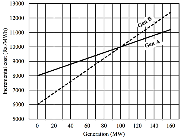
Sign in to UnlockThe incremental cost curves of two generators (Gen A and Gen B) in a plant supplying a common load are shown in the figure. If the incremental cost of supplying the common load is Rs. 7400 per MWh, then the common load in MW is ________ (rounded off to the nearest integer).
Explanation Locked!
Unlock this branch to view the explanation, track, bookmark and more.
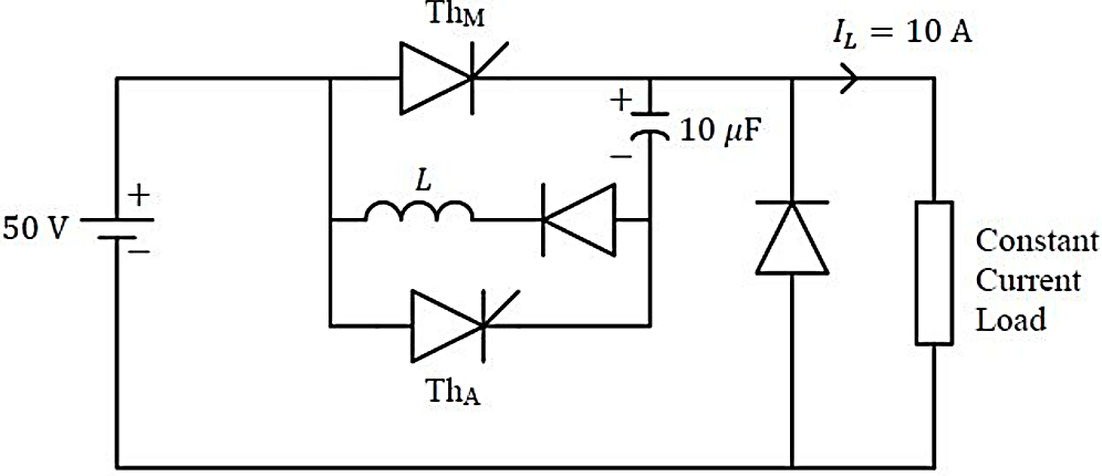
Sign in to UnlockA forced commutated thyristorized step-down chopper is shown in the figure. Neglect the ON-state drop across the power devices. Assume that the capacitor is initially charged to 50 V with the polarity shown in the figure. The load current can be assumed to be constant at 10 A. Initially, is and is OFF. The turn-off time available to in microseconds, when is triggered, is _______ (rounded off to the nearest integer).


Explanation Locked!
Unlock this branch to view the explanation, track, bookmark and more.
Sign in to UnlockConsider a vector , where represent unit vectors along the coordinate axes respectively. The directional derivative of the function at the point in the direction of is


0

7
21
Explanation Locked!
Unlock this branch to view the explanation, track, bookmark and more.
Sign in to UnlockThe input and the output of a system are related as

Explanation Locked!
Unlock this branch to view the explanation, track, bookmark and more.
Sign in to UnlockConsider the discrete-time systems and defined as follows:


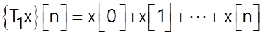
Which one of the following statements is true?
and are BIBO stable.


and are not BIBO stable.
is BIBO stable but is not BIBO stable.
is not BIBO stable but is BIBO stable.
Explanation Locked!
Unlock this branch to view the explanation, track, bookmark and more.
Sign in to UnlockIf the -transform of a finite-duration discrete-time signal is , then the transform of the signal is


Explanation Locked!
Unlock this branch to view the explanation, track, bookmark and more.
Sign in to UnlockA 3-phase, 11kV, 10 MVA synchronous generator is connected to an inductive load of power factor via a lossless line with a per-phase inductive reactance of . The per-phase synchronous reactance of the generator is with negligible armature resistance. If the generator is producing the rated current at the rated voltage, then the power factor at the terminal of the generator is


Explanation Locked!
Unlock this branch to view the explanation, track, bookmark and more.
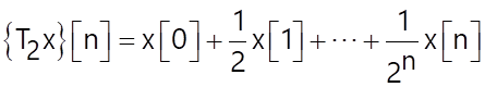
Sign in to UnlockFor the three-bus lossless power network shown in the figure, the voltage magnitudes at all the buses are equal to 1 per unit , and the differences of the voltage phase angles are very small. The line reactances are marked in the figure, where , and are strictly positive. The bus injections and are in pu. If , where , and the real power flow from bus 1 to bus 2 is , then which one of the following options is correct?


Explanation Locked!
Unlock this branch to view the explanation, track, bookmark and more.
Sign in to UnlockA BJT biasing circuit is shown in the figure, where and . The Quiescent Point values of and are respectively


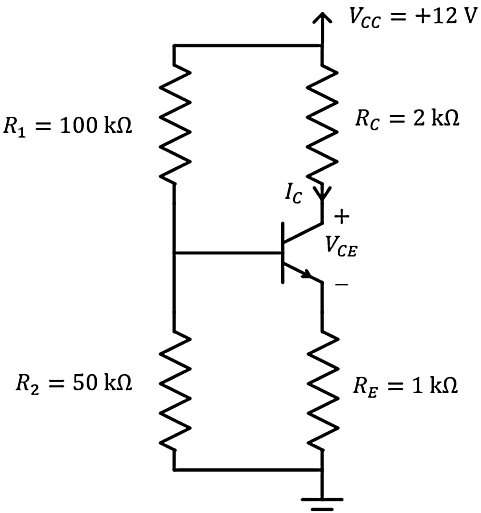
and


and

and


and
Explanation Locked!
Unlock this branch to view the explanation, track, bookmark and more.
Sign in to UnlockLet be a real-valued function whose second derivative is positive for . Which of the following statements is/are always true?


has at least one local minimum.
cannot have two distinct local minima.
has at least one local maximum.
The minimum value of cannot be negative.
Explanation Locked!
Unlock this branch to view the explanation, track, bookmark and more.
Sign in to UnlockConsider the function for , where denotes the maximum of and . Which of the following statements is/are true?


is not differentiable.
is differentiable and its derivative is continuous.
is differentiable but its derivative is not continuous.
and its derivative are differentiable.
Explanation Locked!
Unlock this branch to view the explanation, track, bookmark and more.
Sign in to UnlockTwo passive two-port networks and are connected as shown in the figure. The impedance matrix of network is . The admittance matrix of network is . Let the ABCD matrix of the two-port network in the figure be . The value of in is _______(rounded off to 2 decimal places).


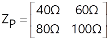
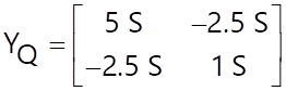


Explanation Locked!
Unlock this branch to view the explanation, track, bookmark and more.
Sign in to UnlockFor the circuit shown in the figure, the source frequency is . The mutual inductance between the magnetically coupled inductors is with their self inductances being and . The Thevenin's impedance, , between the terminals and Q in is _______ (rounded off to 2 decimal places).


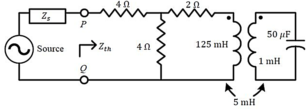
Explanation Locked!
Unlock this branch to view the explanation, track, bookmark and more.
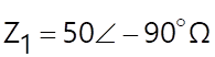
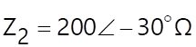
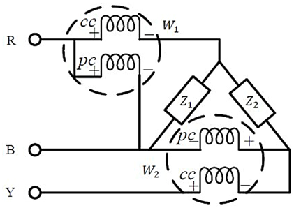
Sign in to UnlockIn the circuit shown, and . It is supplied by a three phase source with the phase sequence being R-Y-B. Assume the watt meters and to be ideal. The magnitude of the difference between the readings of and in watts is _______ (rounded off to 2 decimal places).


Explanation Locked!
Unlock this branch to view the explanation, track, bookmark and more.
Sign in to UnlockIn the coordinate system, three point-charges , and are located in free space at , and , respectively. The value of for the electric field to be zero at is ________(rounded off to 1 decimal place).


Explanation Locked!
Unlock this branch to view the explanation, track, bookmark and more.
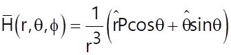
Sign in to UnlockThe given equation represents a magnetic field strength in the spherical coordinate system, in free space. Here, and represent the unit vectors along and , respectively. The value of in the equation should be ________ (rounded off to the nearest integer).


Explanation Locked!
Unlock this branch to view the explanation, track, bookmark and more.
Sign in to UnlockIf the energy of a continuous-time signal is and the energy of the signal is , then is ________ (rounded off to 1 decimal place).


Explanation Locked!
Unlock this branch to view the explanation, track, bookmark and more.
Sign in to UnlockA 3-phase star connected slip ring induction motor has the following parameters referred to the stator:
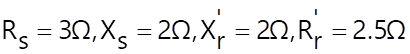
The per phase stator to rotor effective turns ratio is . The rotor winding is also star connected. The magnetizing reactance and core loss of the motor can be neglected. To have maximum torque at starting, the value of the extra resistance in ohms (referred to the rotor side) to be connected in series with each phase of the rotor winding is ________ (rounded off to 2 decimal places).

Explanation Locked!
Unlock this branch to view the explanation, track, bookmark and more.
Sign in to UnlockA DC shunt motor has armature resistance including brushes. The motor draws a no-load current of . The field current is constant at . Assuming that the core and rotational losses are constant and independent of the load, the current (in amperes) drawn by the motor while delivering the rated load, for the best possible efficiency, is ________ (rounded off to 2 decimal places).


Explanation Locked!
Unlock this branch to view the explanation, track, bookmark and more.
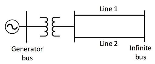
Sign in to UnlockThe single line diagram of a lossless system is shown in the figure. The system is operating in steady-state at a stable equilibrium point with the power output of the generator being , where is the load angle and the mechanical power input is . A fault occurs on line 2 such that the power output of the generator is less than during the fault. After the fault is cleared by opening line 2 , the power output of the generator is . If the critical fault clearing angle is radians, the accelerating area on the power angle curve is ________times (rounded off to 2 decimal places).


Explanation Locked!
Unlock this branch to view the explanation, track, bookmark and more.
Sign in to UnlockConsider the closed-loop system shown in the figure with

The root locus for the closed-loop system is to be drawn for . The angle of departure (between and ) of the root locus branch drawn from the pole , in degrees, is __________ (rounded off to the nearest integer)


Explanation Locked!
Unlock this branch to view the explanation, track, bookmark and more.
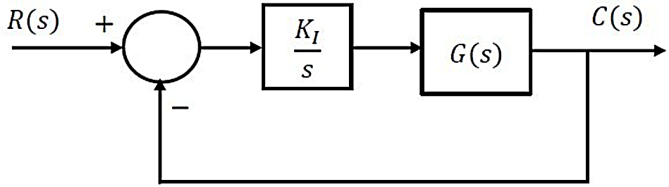
Sign in to UnlockConsider the stable closed-loop system shown in the figure. The asymptotic Bode magnitude plot of has a constant slope of decade at least till with the gain crossover frequency being . The asymptotic Bode phase plot remains constant at at least till . The steady-state error of the closed-loop system for a unit ramp input is ________ (rounded off to 2 decimal places).


Explanation Locked!
Unlock this branch to view the explanation, track, bookmark and more.
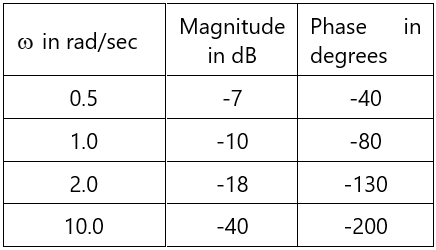
Sign in to UnlockConsider the stable closed-loop system shown in the figure. The magnitude and phase values of the frequency response of are given in the table. The value of the gain for a phase margin is ________ (rounded off to 2 decimal places).


Explanation Locked!
Unlock this branch to view the explanation, track, bookmark and more.
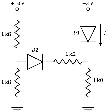
Sign in to UnlockIn the given circuit, the diodes are ideal. The current through the diode in milliamperes is ________ (rounded off to two decimal places).

Explanation Locked!
Unlock this branch to view the explanation, track, bookmark and more.
Sign in to UnlockA difference amplifier is shown in the figure. Assume the op-amp to be ideal. The CMRR (in ) of the difference amplifier is ________ (rounded off to 2 decimal places).

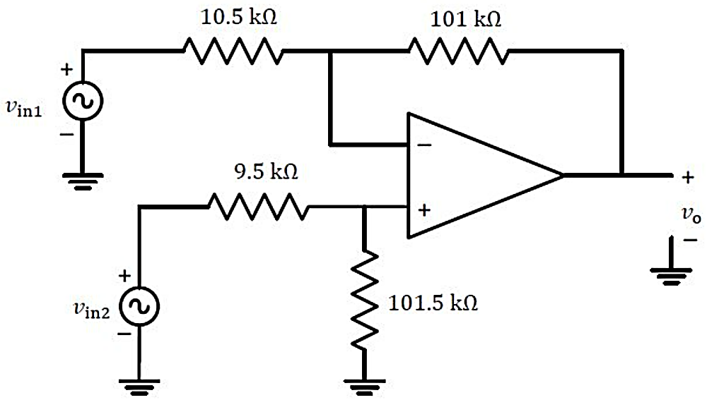
Explanation Locked!
Unlock this branch to view the explanation, track, bookmark and more.
Sign in to UnlockA single-phase half-controlled bridge converter supplies an inductive load with ripple free load current. The triggering angle of the converter is . The ratio of the rms value of the fundamental component of the input current to the rms value of the total input current of the bridge is ________ (rounded off to 3 decimal places).
Explanation Locked!
Unlock this branch to view the explanation, track, bookmark and more.
Sign in to UnlockA single-phase full bridge voltage source inverter (VSI) feeds a purely inductive load. The inverter output voltage is a square wave in conduction mode. The fundamental frequency of the output voltage is 50 Hz. If the DC input voltage of the inverter is 100 V and the value of the load inductance is 20mH, the peak-to peak load current in amperes is ________ (rounded off to the nearest integer).

Explanation Locked!
Unlock this branch to view the explanation, track, bookmark and more.
Sign in to UnlockIn the DC-DC converter shown in the figure, the current through the inductor is continuous. The switching frequency is 500 Hz. The voltage across the load is assumed to be constant and ripple free. The peak inductor current in amperes is ________(rounded off to the nearest integer).

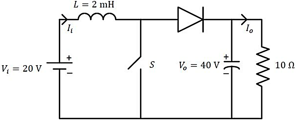
Explanation Locked!
Unlock this branch to view the explanation, track, bookmark and more.
Sign in to UnlockA single-phase full-controlled thyristor converter bridge is used for regenerative braking of a separately excited DC motor with the following specifications:
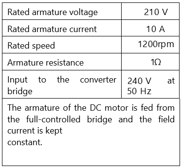
Assume that the motor is running at 600rpm and the armature terminals of the motor are suitably reversed for regenerative braking. If the armature current of the motor is to be maintained at the rated value, the triggering angle of the converter bridge in degrees should be ________ (rounded off to 2 decimal places).
Explanation Locked!
Unlock this branch to view the explanation, track, bookmark and more.
Sign in to UnlockTo obtain the Boolean function , the inputs in the figure should be


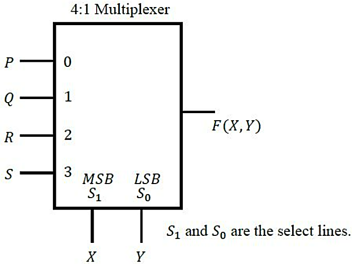
Explanation Locked!
Unlock this branch to view the explanation, track, bookmark and more.
Sign in to UnlockLet be a discrete random variable that is uniformly distributed over the set . Which of the following random variables is/are uniformly distributed?


Explanation Locked!
Unlock this branch to view the explanation, track, bookmark and more.
Sign in to UnlockWhich of the following differential equations is/are nonlinear?
,


,

,

,

Explanation Locked!
Unlock this branch to view the explanation, track, bookmark and more.
Sign in to UnlockFor a two-phase network, the phase voltages and are to be expressed in terms of sequence voltages and as . The possible option(s) for matrix S is/are


Explanation Locked!
Unlock this branch to view the explanation, track, bookmark and more.
Sign in to UnlockWhich of the following options is/are correct for the Automatic Generation Control (AGC) and Automatic Voltage Regulator (AVR) installed with synchronous generators?
Explanation Locked!
Unlock this branch to view the explanation, track, bookmark and more.
Sign in to Unlock