
Consider the set of points which minimize the real valued function


Which of the following statements is true about the set S?
Explanation Locked!
Unlock this branch to view the explanation, track, bookmark and more.
Sign in to UnlockLet and be the two eigenvectors corresponding to distinct eigenvalues of a real symmetric matrix. Which one of the following statements is true?


Explanation Locked!
Unlock this branch to view the explanation, track, bookmark and more.
Sign in to UnlockLet , and . Then, the system of linear equations has


Explanation Locked!
Unlock this branch to view the explanation, track, bookmark and more.
Sign in to UnlockLet and let I can be identity matrix. Then is equal to


Explanation Locked!
Unlock this branch to view the explanation, track, bookmark and more.
Sign in to UnlockConsider discrete random variables and with probabilities as follows:


Given , the expected value of is


Explanation Locked!
Unlock this branch to view the explanation, track, bookmark and more.
Sign in to UnlockWhich one of the following statements is true about the small signal voltage gain of a MOSFET based single stage amplifier?
Explanation Locked!
Unlock this branch to view the explanation, track, bookmark and more.
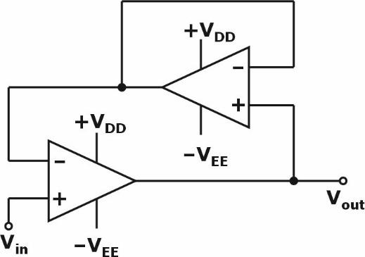
Sign in to UnlockAssuming ideal op-amps, the circuit represents a
Explanation Locked!
Unlock this branch to view the explanation, track, bookmark and more.
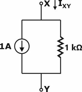
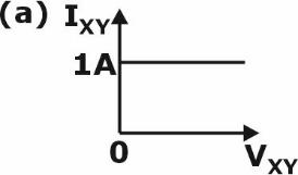
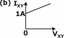
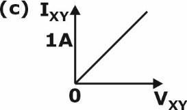
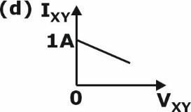
Sign in to UnlockThe I-V characteristics of the element between the nodes X and Y is best depicted by
Explanation Locked!
Unlock this branch to view the explanation, track, bookmark and more.
Sign in to UnlockA nullator is defined as a circuit element where the voltage across the device and the current through the device are both zero. A series combination of a nullator and a resistor of value, R, will behave as a
Explanation Locked!
Unlock this branch to view the explanation, track, bookmark and more.
Sign in to UnlockConsider a discrete-time linear time-invariant (LTI) system , where


Let

where is the discrete-time unit impulse function. For an input signal , the output is


Explanation Locked!
Unlock this branch to view the explanation, track, bookmark and more.
Sign in to UnlockConsider a continuous-time signal

where is the continuous-time unit step function. Let be the continuous time unit impulse function. The value of is


Explanation Locked!
Unlock this branch to view the explanation, track, bookmark and more.
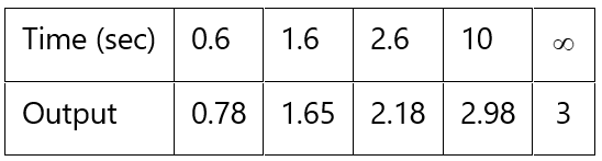
Sign in to UnlockSelected data points of the step response of a stable first-order linear time-invariant (LTI) system are given below. The closest value of the time-constant, in sec, of the system is
Explanation Locked!
Unlock this branch to view the explanation, track, bookmark and more.
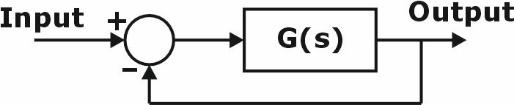
Sign in to UnlockThe Nyquist plot of a strictly stable having the numerator polynomial as encircles the critical point -1 once in the anti-clockwise direction. Which one of the following statements on the closed-loop system shown in figure, is correct?


Explanation Locked!
Unlock this branch to view the explanation, track, bookmark and more.
Sign in to UnlockDuring a power failure, a domestic household uninterruptible power supply (UPS) supplies AC power to a limited number of lights and fans in various rooms. As per a Newton-Raphson load-flow formulation, the UPS would be represented as a
Explanation Locked!
Unlock this branch to view the explanation, track, bookmark and more.
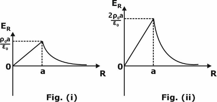
Sign in to UnlockWhich one of the following figures represents the radial electric field distribution caused by a spherical cloud of electrons with a volume charge density, for (both are positive and is the radial distance) and for ?


Explanation Locked!
Unlock this branch to view the explanation, track, bookmark and more.
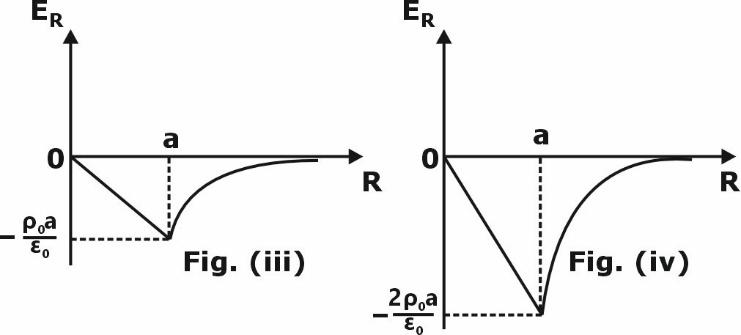
Sign in to UnlockThe operating region of the developed torque and speed () of an induction motor drive is given by the shaded region OQRE in the figure. The load torque characteristic is also shown. The motor drive moves from the initial operating point O to the final operating point S. Which one of the following trajectories will take the shortest time?


Explanation Locked!
Unlock this branch to view the explanation, track, bookmark and more.
Sign in to UnlockThe input voltage and current of a converter are given by,


where, . The input power factor of the converter is closest to

Explanation Locked!
Unlock this branch to view the explanation, track, bookmark and more.
Sign in to UnlockInstrument(s) required to synchronize an alternator to the grid is/are
Explanation Locked!
Unlock this branch to view the explanation, track, bookmark and more.
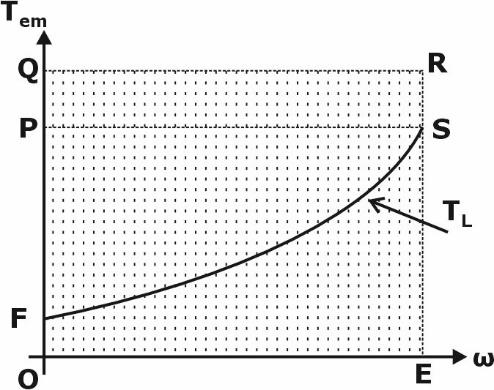
Sign in to UnlockThe open-loop transfer function of the system shown in the figure, is

For , which of the following real axis point(s) is/are on the root locus?

Explanation Locked!
Unlock this branch to view the explanation, track, bookmark and more.
Sign in to UnlockA continuous time periodic signal x(t) is

If is the period of , then __________ (round off to the nearest integer).


Explanation Locked!
Unlock this branch to view the explanation, track, bookmark and more.
Sign in to UnlockThe maximum percentage error in the equivalent resistance of two parallel-connected resistors of and with each having a maximum error is _________ % (round off to nearest integer value).


Explanation Locked!
Unlock this branch to view the explanation, track, bookmark and more.
Sign in to UnlockConsider a distribution feeder, with ratio of 5. At the receiving end, a 350 kVA load is connected. The maximum voltage drop will occur from the sending end to the receiving end, when the power factor of the load is ________ (round off to three decimal places).

Explanation Locked!
Unlock this branch to view the explanation, track, bookmark and more.
Sign in to UnlockThe bus impedance matrix of a 3-bus system (in pu) is

A symmetrical fault (through a fault impedance of ) occurs at bus 2. Neglecting pre-fault loading conditions, the voltage at bus 1 , during the fault is __________ pu (round off to three decimal places).

Explanation Locked!
Unlock this branch to view the explanation, track, bookmark and more.
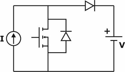
Sign in to UnlockIn the circuit with ideal devices, the power MOSFET is operated with a duty cycle of 0.4 in a switching cycle with and . The power delivered by the current source, in W, is __________ (round off to the nearest integer).


Explanation Locked!
Unlock this branch to view the explanation, track, bookmark and more.
Sign in to UnlockThe induced emf in a pole, 3-phase star connected synchronous motor is considered to be equal and in phase with the terminal voltage under no load condition. On application of a mechanical load, the induced emf phasor is deflected by an angle of mechanical with respect to the terminal voltage phasor. If the synchronous reactance is , and stator resistance is negligible, then the motor armature current magnitude, in ampere, during loaded condition is closest to, _________ (round off to two decimal places).


Explanation Locked!
Unlock this branch to view the explanation, track, bookmark and more.
Sign in to UnlockLet and be continuous random variables with probability density functions and , respectively. Further, let and


Which one of the following options is correct?


Explanation Locked!
Unlock this branch to view the explanation, track, bookmark and more.
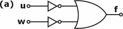
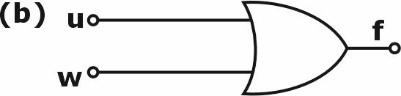
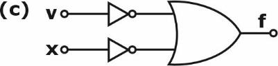
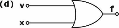
Sign in to UnlockA Boolean function is given as

The simplified form of this function is represented by
Explanation Locked!
Unlock this branch to view the explanation, track, bookmark and more.
Sign in to UnlockIn the circuit, is an ideal current source. The transistors and are assumed to be biased in saturation, wherein is the input signal and is fixed DC voltage. Both transistors have a small signal resistance of and trans-conductance of . The small signal output impedance of this circuit is


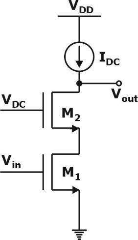


infinity
Explanation Locked!
Unlock this branch to view the explanation, track, bookmark and more.
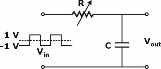
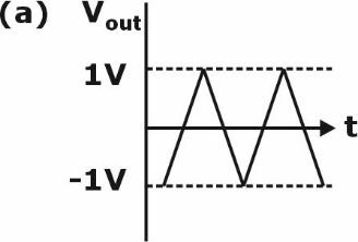
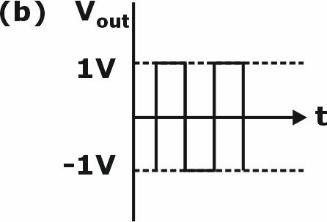
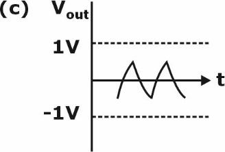
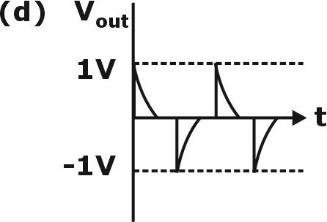
Sign in to UnlockIn the circuit, shown below, if the values of R and C are very large, the form of the
output voltage for a very high frequency square wave input, is best represented by
Explanation Locked!
Unlock this branch to view the explanation, track, bookmark and more.
Sign in to UnlockLet continuous-time signals and be


Consider the convolution . Then is


Explanation Locked!
Unlock this branch to view the explanation, track, bookmark and more.
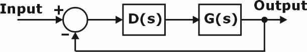
Sign in to UnlockLet . Then the closed-loop system shown in the figure below, is

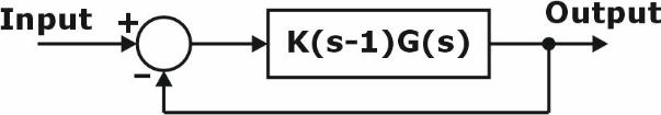
stable for all .

unstable for all .
unstable for all .

stable for all .
Explanation Locked!
Unlock this branch to view the explanation, track, bookmark and more.
Sign in to UnlockThe continuous-time unit impulse signal is applied as an input to a continuous-time linear time-invariant system . The output is observed to be the continuous-time unit step signal . Which one of the following statements is true?


Every bounded input signal applied to results in a bounded output signal.
It is possible to find a bounded input signal which when applied to results in an unbounded output signal.
On applying any input signal to , the output signal is always bounded.
On applying any input signal to the output signal is always unbounded.
Explanation Locked!
Unlock this branch to view the explanation, track, bookmark and more.
Sign in to UnlockThe transformer connection given in the figure is part of a balanced 3-phase circuit where the phase sequence is "". The primary to secondary turns ratio is . If , then the relationship between and will be


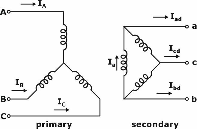
and lags by .


and leads by .
and lags by .

and leads by .
Explanation Locked!
Unlock this branch to view the explanation, track, bookmark and more.
Sign in to UnlockA DC series motor with negligible series resistance is running at a certain speed driving a load, where the load torque varies as cube of the speed. The motor is fed from a 400 V DC source and draws 40 A armature current. Assume linear magnetic circuit. The external resistance, in , that must be connected in series with the armature to reduce the speed of the motor by half, is closest to

Explanation Locked!
Unlock this branch to view the explanation, track, bookmark and more.
Sign in to UnlockA 3-phase, pole, 50 Hz star connected induction motor has the following parameters referred to the stator:


Stator resistance, magnetizing reactance and core loss of the motor are neglected. The motor is run with constant control from a drive. For maximum starting torque, the voltage and frequency output, respectively, from the drive, is closest to,

Explanation Locked!
Unlock this branch to view the explanation, track, bookmark and more.
Sign in to UnlockThe 3-phase modulating waveforms and , used in sinusoidal PWM in a Voltage Source Inverter (VSI) are


where is the fundamental frequency. The modulating waveforms are compared with a 10 kHz triangular carrier whose magnitude varies between +1 and -1. The VSI has a DC link voltage of 600 V and feeds a star connected motor. The per phase fundamental RMS motor voltage, in volts, is closest to

Explanation Locked!
Unlock this branch to view the explanation, track, bookmark and more.
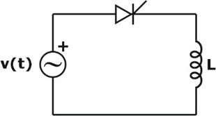
Sign in to Unlockfeeds an ideal inductor through an ideal SCR with firing angle . If , then the peak of the inductor current, in ampere, is closest to


Explanation Locked!
Unlock this branch to view the explanation, track, bookmark and more.
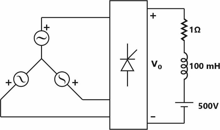
Sign in to UnlockIn the following circuit, the average voltage

where is the firing angle. If the power dissipated in the resistor is 64 W, then the closest value of in degrees is

Explanation Locked!
Unlock this branch to view the explanation, track, bookmark and more.
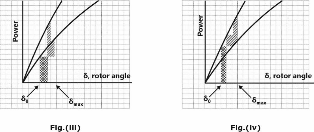
Sign in to UnlockIn the system shown below, the generator was initially supplying power to the grid. A temporary LLLG bolted fault occurs at F very close to circuit breaker 1. The circuit breakers open to isolate the line. The fault self-clears. The circuit breakers reclose and restore the line. Which one of the following diagrams best indicates the rotor accelerating and decelerating areas?

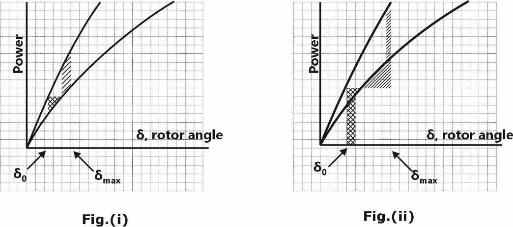
Explanation Locked!
Unlock this branch to view the explanation, track, bookmark and more.
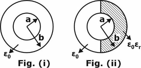
Sign in to UnlockAn air filled cylindrical capacitor (capacitance ) of length , with and as its inner and outer radii, respectively, consists of two coaxial conducting surfaces. Its cross-sectional view is shown in Fig. (i). In order to increase the capacitance, a dielectric material of relative permittivity is inserted inside of the annular region as shown in Fig. (ii). The value of for which the capacitance of the capacitor in Fig. (ii), becomes is


Explanation Locked!
Unlock this branch to view the explanation, track, bookmark and more.
Sign in to UnlockLet be the unit radial vector in the spherical co-ordinate system. For which of the following value(s) of , the divergence of the radial vector field is independent of ?


1
2
Explanation Locked!
Unlock this branch to view the explanation, track, bookmark and more.
Sign in to UnlockConsider two coupled circuits, having self-inductances and , that carry nonzero currents and , respectively. The mutual inductance between the circuits is with unity coupling coefficient. The stored magnetic energy of the coupled circuits is minimum at which of the following value(s) of ?


Explanation Locked!
Unlock this branch to view the explanation, track, bookmark and more.
Sign in to UnlockLet . The rate of change of the real valued function,


at the origin in the direction of the point is __________ (round off to the nearest integer).

Explanation Locked!
Unlock this branch to view the explanation, track, bookmark and more.
Sign in to UnlockConsider ordinary differential equations given by


with initial conditions and .


If , then at __________ (round off to the nearest integer).


Explanation Locked!
Unlock this branch to view the explanation, track, bookmark and more.
Sign in to UnlockLet be a clockwise oriented closed curve in the complex plane defined by . Further, let be a complex function, where . Then, __________ (round off to the nearest integer).


Explanation Locked!
Unlock this branch to view the explanation, track, bookmark and more.
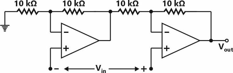
Sign in to UnlockThe op-amps in the following circuit are ideal. The voltage gain of the circuit is ________ (round off to the nearest integer).
Explanation Locked!
Unlock this branch to view the explanation, track, bookmark and more.
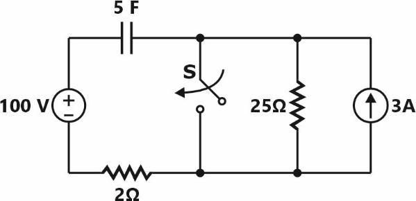
Sign in to UnlockThe switch (S) closes at . The time, in sec, the capacitor takes to charge to 50 V is ________ (round off to one decimal place).

Explanation Locked!
Unlock this branch to view the explanation, track, bookmark and more.
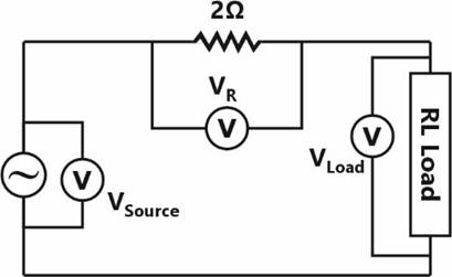
Sign in to UnlockIn an experiment to measure the active power drawn by a single-phase RL Load connected to an AC source through a resistor, three voltmeters are connected as shown in the figure below. The voltmeter readings are as follows: . Assuming perfect resistors and ideal voltmeters, the Load-active power measured in this experiment, in W, is __________ (round off to one decimal place).


Explanation Locked!
Unlock this branch to view the explanation, track, bookmark and more.
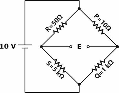
Sign in to UnlockIn the Wheatstone bridge shown below, the sensitivity of the bridge in terms of change in balancing voltage for unit change in the resistance , in , is __________ (round off to two decimal places).


Explanation Locked!
Unlock this branch to view the explanation, track, bookmark and more.
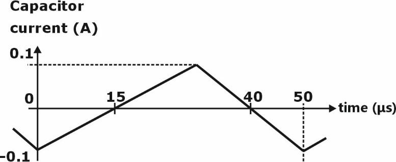
Sign in to UnlockThe steady state capacitor current of a conventional DC-DC buck converter, working in CCM, is shown in one switching cycle. If the input voltage is 30 V, the value of the inductor used, in mH, is ________ (round off to one decimal place).
Explanation Locked!
Unlock this branch to view the explanation, track, bookmark and more.
Sign in to UnlockAn ideal low pass filter has frequency response given by

Let be its time domain representation. Then __________ (round off to the nearest integer).


Explanation Locked!
Unlock this branch to view the explanation, track, bookmark and more.
Sign in to UnlockConsider the state-space model


where are the state, input and output, respectively. The matrices are given below


The sum of the magnitudes of the poles is __________ (round off to nearest integer).
Explanation Locked!
Unlock this branch to view the explanation, track, bookmark and more.
Sign in to UnlockUsing shunt capacitors, the power factor of a 3 -phase, 4 kV induction motor (drawing 390 kVA at 0.77 pf lag) is to be corrected to 0.85 pf lag. The line current of the capacitor bank, in A, is _________ (round off to one decimal place).
Explanation Locked!
Unlock this branch to view the explanation, track, bookmark and more.
Sign in to UnlockTwo units, rated at 100 MW and 150 MW, are enabled for economic load dispatch. When the overall incremental cost is 10,000 Rs./MWh, the units are dispatched to 50 MW and 80 MW respectively. At an overall incremental cost of , the power output of the units are 80 MW and 92 MW, respectively. The total plant MW-output (without overloading any unit) at an overall incremental cost of is __________ (round off to the nearest integer).


Explanation Locked!
Unlock this branch to view the explanation, track, bookmark and more.
Sign in to UnlockA controller of the form is to be designed for the plant as shown in the figure. The value of that yields a phase margin of at the gain cross-over frequency of is ___________ (round off to one decimal place).


Explanation Locked!
Unlock this branch to view the explanation, track, bookmark and more.
Sign in to Unlock