
Login to track your progress, bookmark questions, and view history.
Q#1
Sequential Circuits
GATE EC 2025
MCQ
+2 marks
-0.66 marks
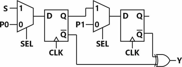
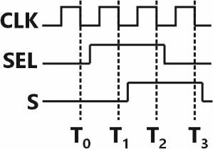
A positive-edge-triggered sequential circuit is shown below. There are no timing violations in the circuit. Input is set to logic ' 0 ' and is set to logic ' 1 ' at all times. The timing diagram of the inputs and are also shown below.




The sequence of output from time to is ________.



Sign in to see the solution
Log in to view the explanation, track your attempts, and keep your progress.
Sign in to Unlock
Login to keep track of your progress with the tool with daily goals, questions preparation and more.
Browse Practice Questions by Chapters / Topics in Browse Practice Questions by Chapters / Topics in GATE Electronics and Communications
Total Questions
Attempted
% Attempted
Correct
% Correct
Login to keep track of your progress with the tool with daily goals, questions preparation and more.
| Topic | Questions | Attempted | Correct | |
|---|---|---|---|---|
| Network Analysis | 273 | 0 | 0 | |
| Electronic Devices | 69 | 0 | 0 | |
| Analog Electronics | 395 | 0 | 0 | |
| Digital Electronics | 351 | 0 | 0 | |
| Signals and Systems | 22 | 0 | 0 | |
| Control Systems | 224 | 0 | 0 | |
| Communication System | 200 | 0 | 0 | |
| EMFT - ECE | 14 | 0 | 0 | |
| Engineering Mathematics | 24 | 0 | 0 | |
| General Aptitude | 30 | 0 | 0 |